Introduction
The goal of this project is to create a device that replicates the functions of a Speedstacks Tournament Display, which retails for about $95 in the US.
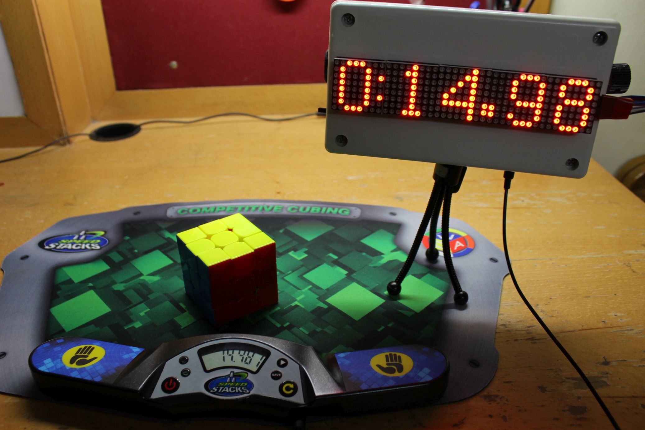
This has a 6 digit 7-segment display panel, and plugs into a stackmat timer via a standard audio jack. The stackmat outputs whatever time is on its display through a series of digital pulses. These pulses are received by the display and processed to convert them back to regular integers. Finally the time is displayed on the large 7-segment panel.
As seen in the photo above, this project only shows 5 digits, so the thousandth digit is omitted. However, this does not prevent it from being used in competitions until WCA regulations change.
I also want to keep the software and hardware completely open source, so that anyone can use it and improve upon it in the future.
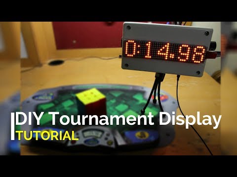
Here is a video showcasing the features of the final product:
Click here to skip the technical stuff and go straight to the instructions.
The data transmission protocol
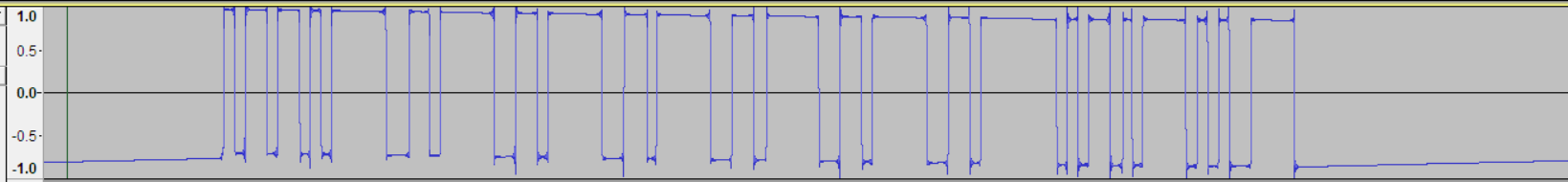
This is what the audio signal output by the stackmat looks like, when it is at 0:00:00. It was recorded with audacity from a computer through the audio jack. The timer outputs such a signal about every 0.15 seconds, giving the current state of the timer. The first task is to be able to decode this data.
Since I did not discover this on my own, I’m just going to link a couple of sources that explain the serial protocol. The first is from the ‘Selfmade Stackmat Display’ by German programmer Florian Weingarten back in 2008. It was something very similar to what I did, except he used discrete components and a custom PCB, which means it would be very hard to make for anyone who is not familiar with electronics. It was encased in a box with a 7-segment display panel and buttons to save times and display averages. You can see what it looked like here.
Unfortunately, the tutorial he posted has long been taken down. We can only access the text using a web cache. Scroll down to the ‘How it works’ section for an explanation of the protocol. http://web.archive.org/web/20100820185842/http://hackvalue.de:80/hv_atmel_stackmat
The second source is reddit user /u/freundTech. He made a project to control TwistyTimer from a G4 stackmat. Here is his comment with an excellent explanation of the protocol:
History of stackmat timer hacks
The earliest one I could find was the display by Florian that I described in the previous section. In 2014, Jeremy Fleischman (creator of TNoodle, the official WCA scrambling software) posted this on his website: Dialup Stackmat
It’s a really well written article that describes his progress in making a stackmat connect directly to a phone. He discovered that different phones filter the incoming audio signal very differently, and so getting a software based solution that works on all phones is near impossible. He was forced to make a custom PCB to shift the signal to frequencies that phones do not filter. While this is a great solution, it requires him to mass produce and ship those boards himself, in order to keep cost per unit low.
The speedsolving forums thread where Jeremy posted about his project has a couple of replies from people who have successfully connected stackmats to their phones.
In 2015, CubeWizard23 and his brother made and sold a 7-segment display based stackmat display for $37.50. They seem to have used an Arduino and a MAX232 chip to decode the stackmat data. It was a very robust design with a hard plastic case and tripod socket. They have not released any significant information about how they put their project together.
More recently, reddit user /u/freundTech used a new feature in Android 7.0 that allows unprocessed audio input to directly connect a stackmat with his customised version of Twisty Timer. Like the previous one, this solution too is device specific, and getting it to work on other android phones is a hit or miss.
I’ll return to the issue of phone-stackmat linking at the very end of this page.
Voltage level of stackmat timers
From Florian’s article:
The “stackmat signal” is essentially just a RS232 serial signal (1200 baud, 8 databits, no parity bits, one stop bit). This signal is converted to TTL level (5V/0V) by the MAX232 level shifter IC, so the Atmel microprocessor can understand it.
He is saying that we need an IC called MAX232 to transform the signal coming from the stackmat in order for the Arduino to be able to understand it. Since I did not have any experience with using this IC, I decided to take a look at the signal and see if there was some other way to process it, perhaps by simply amplifying it.
Not having access to an oscilloscope at the time, I simply gave the stackmat to an Arduino’s analog pin and serially printed the readings and hoped that it wouldn’t destroy the Arduino (because proper RS232 actually goes up to 15V, which would pretty much fry the board). To my surprise, the output looked perfectly like it was supposed to.
It turns out that stackmat simply uses a voltage level of 0 to 3 volts, as suggested by the 2 x 1.5V AAA batteries it runs on. According the electrical characteristics of the Atmega328 (the microcontroller the Arduino is based around), the minimum an input voltage must be, to be considered a logical high (i.e. the VIH_min) is 0.6 times the VCC. For a VCC of 5-5.2V (which we can get from a computer’s USB port), this gives a VIH_min of slightly above 3V, which is exactly what the stackmat is giving out!
Admittedly, the voltage is quite close to the edge, and there might be some issues when the stackmat batteries run low. But I have not had any problems yet.
In conclusion, there is no need for any voltage level shifter, and this makes the project much simpler to build.
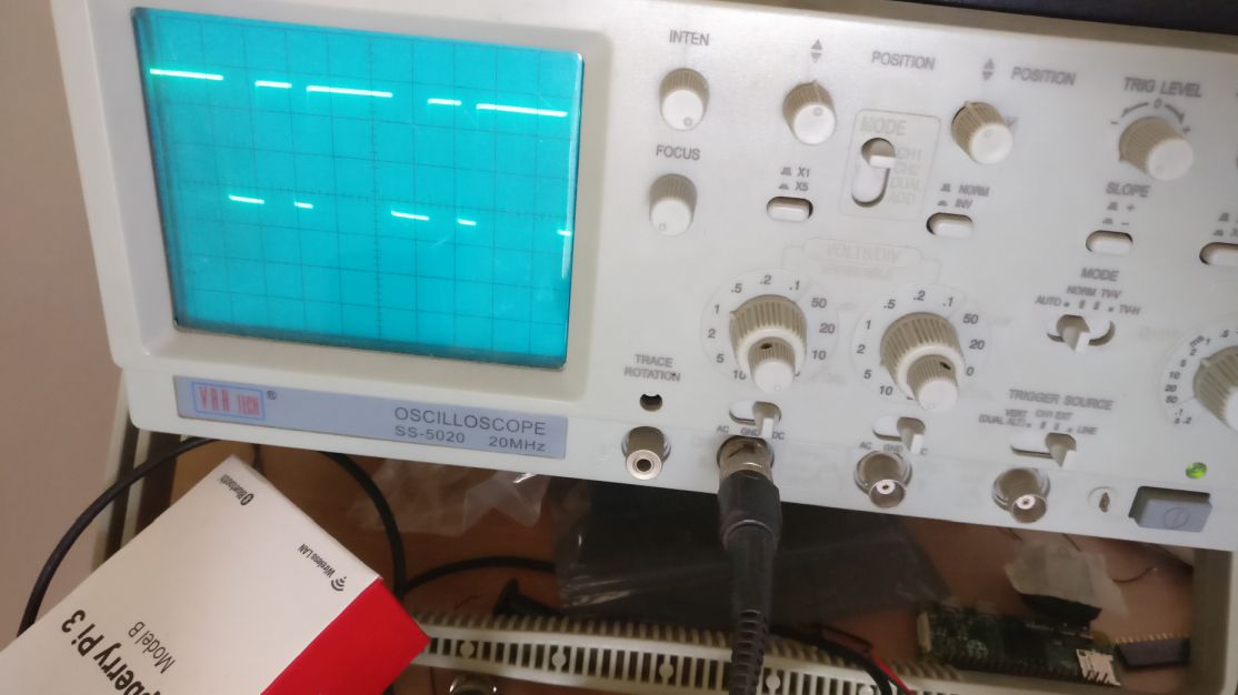
I later confirmed this with an oscilloscope:
Making a display: 7-segment LEDs or LED Matrix?
So far, we can see that 7-segment LEDs are the main choice for people making stackmat displays. This is because they are available in a wide variety of sizes and colors. However, each digit has 10 pins, therefore a total of 50 pins would need to be connected for a 5 digit display.
No microcontroller supports so many outputs, so we have to use a chip called the MAX7219 that takes up the task of driving up to 8 7-segment digits. Since even this chip does not have a lot of pins, it achieves the required functionality by multiplexing – i.e. turning on a digit, holding it for a few microseconds, turning it off and moving on to the next digit. This gives the impression of all the digits being on when viewed by the human eye. We can, infact achieve the same functionality from the microcontroller, but that will waste valuable processor time that is needed to accurately capture the incoming stackmat signal.
This is the approach taken by the others who have done this project. The wiring diagram would look something link this:
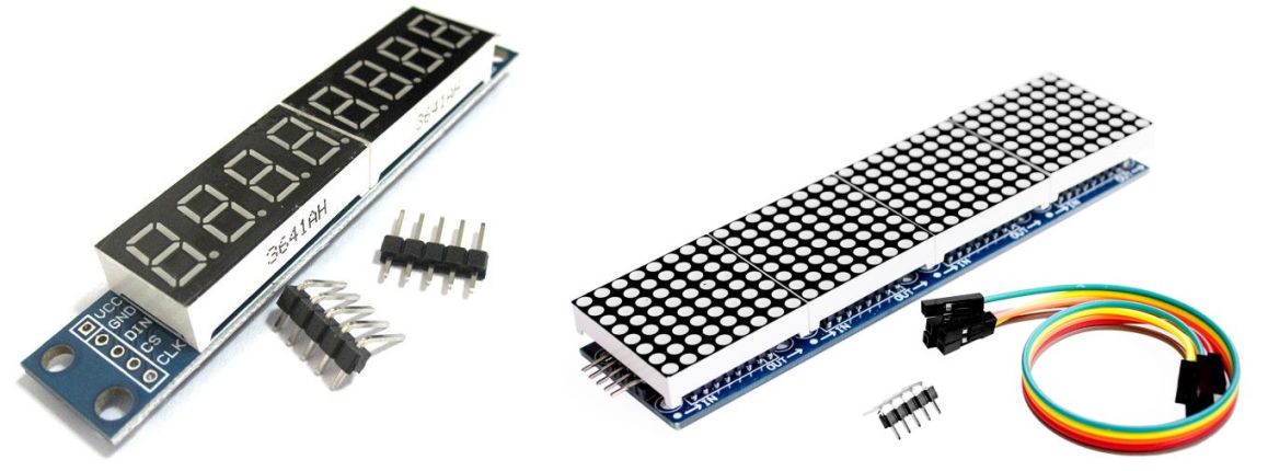
Since this is quite an extensive wiring task, a simpler option would be to use preassembled MAX7219-LED boards. Such boards are in fact available for quite a low price (~$1). The main pitfall is that these are only available in tiny sizes, usually with 0.5” high digits. The resulting stackmat display would not be very clearly visible from more than a few feet away in a competition setting.
This leaves us with the final option: preassembled MAX7219 Dot-matrix LED boards. These cost significantly more than 7-segment boards, but are much bigger at about 1.2” and offer much greater customisability in what we can display on them. We can have custom fonts, text animation effects and even custom symbols.
They are available in individual 8x8 pixel units, or as chains of four such units. We will use one 4-in-1 unit and one single unit cascaded together.
Block diagram
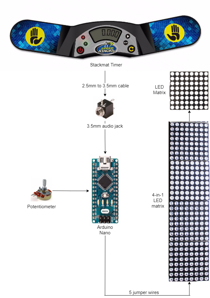
This figure shows the overall big picture of what we are trying to build. We receive the signal from the stackmat’s 2.5mm jack and give it between a digital input pin and ground of an Arduino Nano microcontroller. The Arduino has a program uploaded to it which decodes the incoming data and displays it on the screen in real time.
A potentiometer allows the brightness of the display to be changed by turning a knob.
Power is supplied to the board through the Arduino’s USB port. A small powerbank can be used for this purpose. Alternatively, we can use a discrete Lithium-ion battery with some supporting circuitry.
What you need and where to get it
The best place to buy components is from China, using a site like Aliexpress.com. If you pick the free shipping option, it may take 1-1.5 months for it to reach you, but it is worth it since the prices are very low. It’s worth comparing prices at your local hobby electronics store before ordering.
I’ll provide the cheapest links I can find. Be aware that there is always the risk of the getting the wrong product, or having the product lost in shipment. If that happens, you will have to contact the seller for a refund and try another seller.
An Arduino Nano board. $2.66
Single 8x8 MAX7219 LED matrix. $1.26
4-in-1 MAX7219 LED Matrix. $3.83
2.5mm to 3.5mm, male to male audio cable. $0.97
Female 3.5mm audio jack. $0.93
Female to female jumper wire. $0.59
Some single strand wire. ~$0
Optional: for allowing adjustable brightness
Male header pins $0.31
https://www.aliexpress.com/item/1PCS-40P-2-54mm-Male-Color-Single-Row-Pin-Header/32537378399.html
1K Potentiometer $0.94
This covers all the core components needed for the project, totalling up to just over $11.
Some other tools and components you might require are.
- Soldering rod, lead and flux.
- Wire cutter and stripper
- A box to build the display in. I used a 4x7x2 inches plastic enclosure I got from a local electronics store.
- A tripod, if your box is small and you need to get it off the ground. You can get a cheap one for about a dollar here.
- Hot glue gun
- Insulation tape
- Epoxy (like m-seal) for firmly attaching buttons and knobs to the box.
Video tutorial: complete assembly instructions
Setting up the software environment
- Install the Arduino IDE.
- Download the libraries MD_Parola and MD_MAX2XX using ‘Clone or download’ -> ‘Download ZIP’.
- Extract the ZIPs to get two folders called MD_Parola-master and MD_MAX72XX-master.
- Move these folders to the Documents\Arduino\Libraries folder (On Windows only. more info on library installation can be found here)
- Open MD_MAX72XX-master\src\MD_MAX72XX.h. If it does not display well in notepad, try wordpad.
- Search for USE_PAROLA_HW and replace the 1 next to it with a 0. Search for your hardware (usually USE_FC16_HW, see the full tutorial for more information) and replace the 0 next to it with a 1. Save the file and close it.
- Download this repository and extract the ledmat.ino file. Open it, set the board to Arduino Nano in the Tools menu. Also make sure the correct Port is selected.
- Upload the sketch, plug in the stackmat and enjoy!
Update (24/11/17): The MD_MAX72XX library has been taken down from Github. You can download an older version from this mirror. Since the latest MD_Parola would cause compatibility issues, use this version.
Making a portable power supply unit
You will need:
1. TP4056 Li-ion battery charger module $2.33
2. Li-ion battery $???
I got a 1400 mAh battery for about $2 at my local electronics store. I can’t seem to find any good listings on AliExpress, and there’s also a high chance of it being stopped at Customs (explosion risk and all that).
So just find a decent li-ion or li-po battery that is rated at 3.7 V on eBay or Amazon. Anything over 500 mAh should be good enough. Make sure the battery already has two terminal wires soldered, as doing it yourself can be hard, not to mention dangerous.
3. On/Off Switch $1.59 (100pcs)
Probably way cheaper to buy this locally. You only need one.
4. 5V Step-up module $1.40/$1.69
or
This section definitely requires some soldering skills. You can find tutorials for that on Youtube.
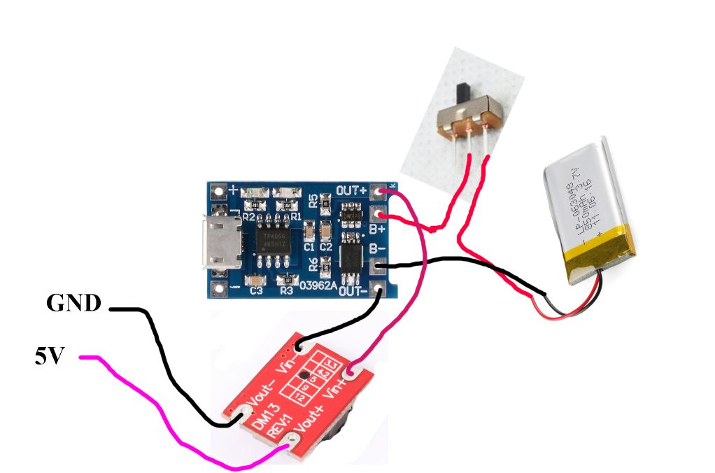
First connect the red wire of the battery to an extreme terminal of the on/off switch. Then the middle terminal of the switch to the terminal marked B+ or BAT+ on the side of the TP4056 board without the USB port. Connect the black wire directly to B- or BAT-. Connections should be made by stripping the insulation around the end of the wire, looping the exposed end through the hole and soldering.
Now connect OUT+ to VIN+ of the step up module, and OUT- to VIN-. If the board has a USB port, you can connect a regular USB to mini-USB cable to it and plus the other end into the Arduino. If not, then there will be two output terminals.
VOUT- should connect to a GND of the Arduino or any GND on the back of the LED matrix. VOUT+ should connect to the 5V pin of the Arduino or a VCC on the back of the LED Matrix. Since we already soldered two small header pins on the back of the display, we can share those points with the potentiometer. This will require stripping the insulation at a convenient point, and soldering.
The Arduino should now turn on when you toggle the switch.
Fitting the project into an enclosure
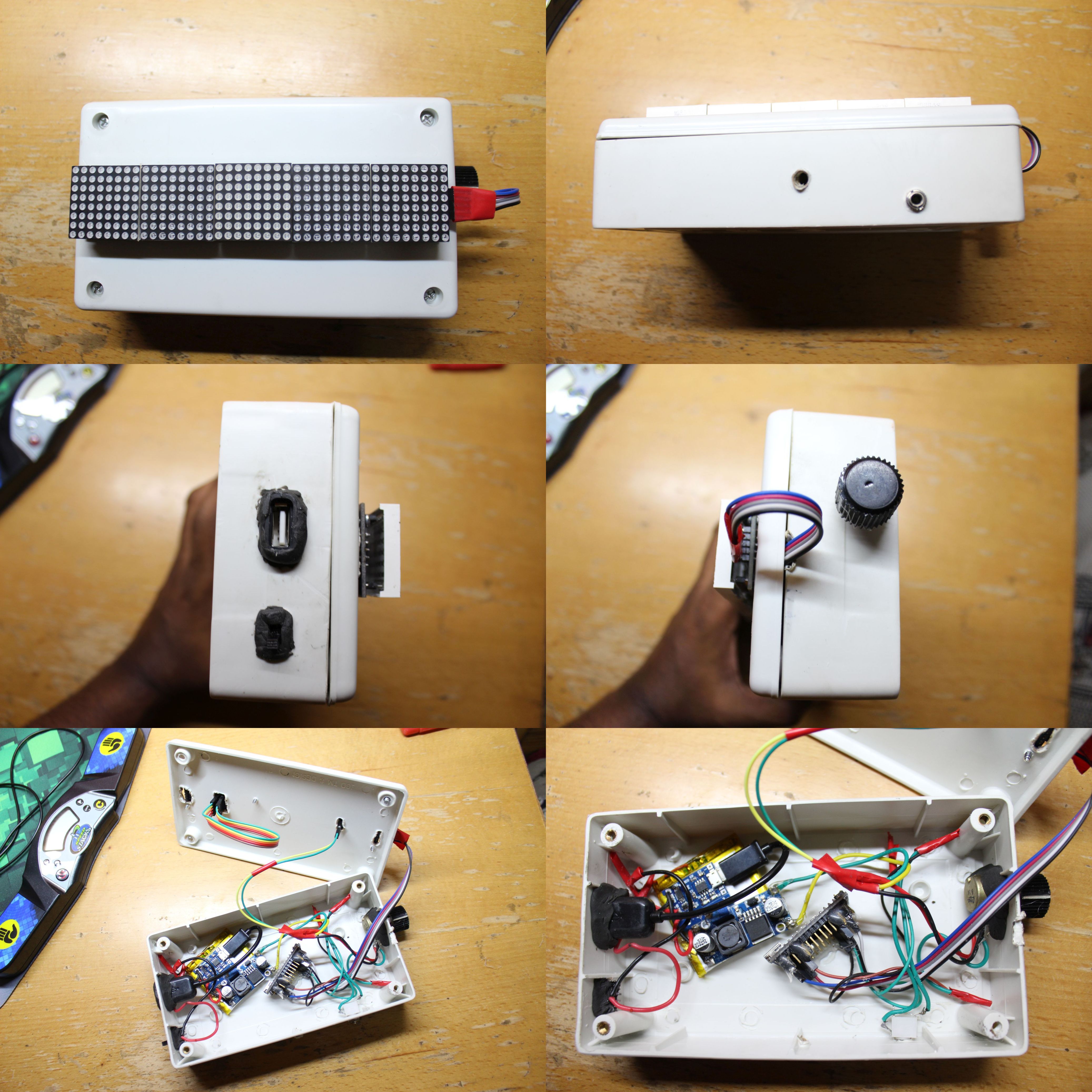
Click on the above image to see the full sized version.
I used a 4”x7”x2” plastic enclosure I got at a local electronics store. It came with 4 screws to secure the front in place.
First I glued the single and 4-in-1 LED matrix units together using hot glue. Next I placed the now 5-in-1 unit on the front of the box and marked the places where the screw holes are. I used only 3 screws, as far away from each other as possible. I made holes for the screws in the front of the box using a heated soldering rod. I also had to make holes to allow the pins protruding from the back to sit inside the case. Then I removed the LED panels from it’s PCB, screwed the boards into the box, and put the panels back. The incoming 5 jumper wires needed a small indentation in the side of the box to not prevent the box from closing.
I hot glued the battery to the inner back wall of the box, and stuck the charger and step-up modules on the battery using double sided-tape. Next, I hot glued the arduino down, taking care to allow enough around its USB port. This is necessary if the code ever needs to be changed.
Using a soldering rod, I made holes on the bottom for the tripod and audio jack. This can be a bit tricky because if the hole gets too big, it’s basically useless. Similarly, I made holes for the switch, potentiometer and an OTG cable that I connected to the TP4056 charger module. I secured these components using epoxy, to prevent them from coming loose due to wear and tear.
More stackmat projects
From the section on the history of stackmat hacks, we can see that connecting directly to a phone has been a rather difficult task. But by introducing the Arduino in the middle, the task of interpreting the data is no longer on the phone.
We can transfer the decoded time data to the phone using a technology that will work the same no matter what the phone is: Bluetooth. The only hardware modification this will require is replacing the two LED matrix panels with a HC-05 bluetooth module. We can then modify any existing open source timer app to work with the Bluetooth module. I will have a tutorial for this linked here shortly.